
CAD Design in Industrial Electrical: Detailed Drawings Prevent Mistakes
When a large-scale industrial electrical project goes wrong, the root cause is rarely the workers on the floor. More often, it traces back upstream to documentation: a drawing that did not reflect the actual installation, a design that was never updated after a change order, or a set of plans that left too much open to interpretation. Accurate, detailed electrical CAD drawings are not a formality. They are a critical tool that protects your schedule, your budget, and your workforce.
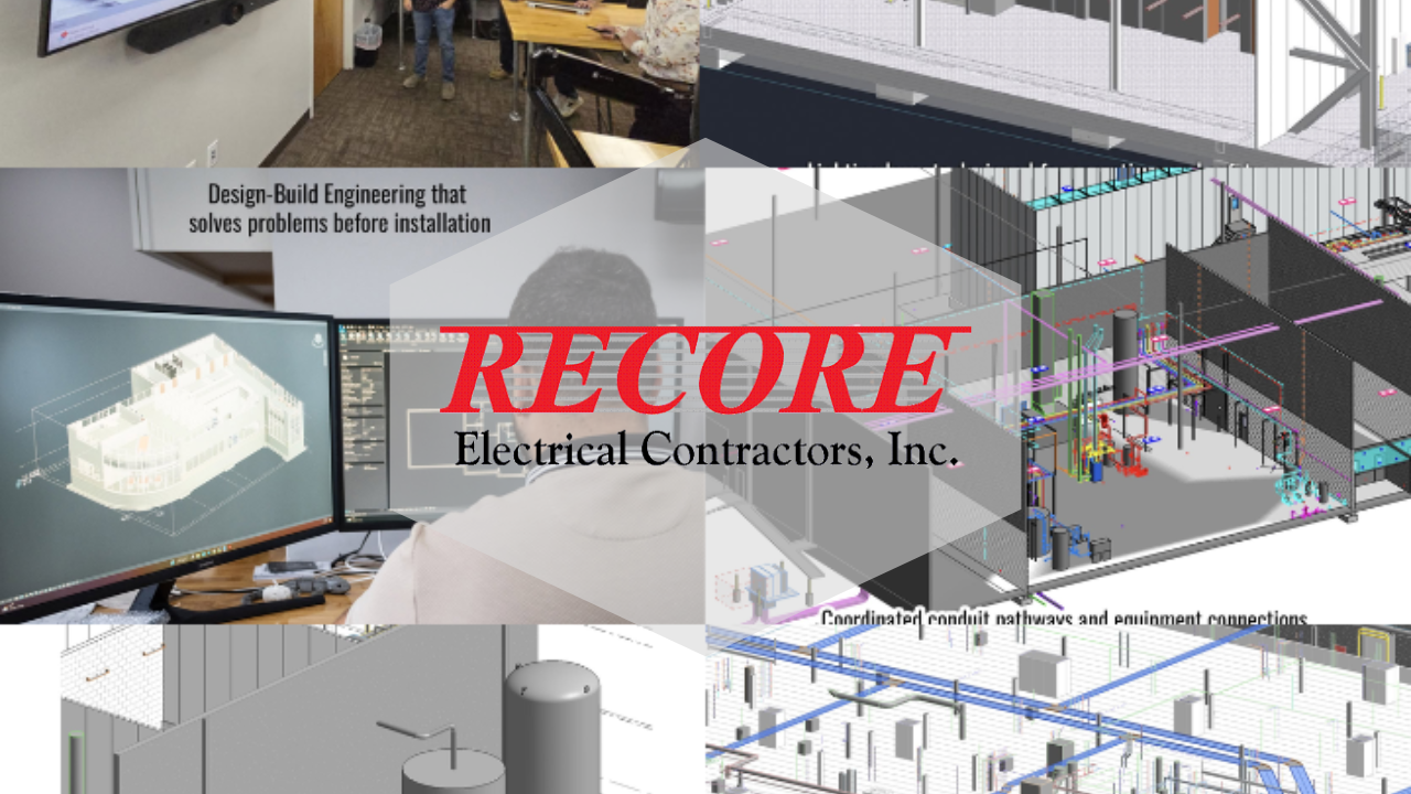
At Recore Electric, our engineering team provides CAD design services for commercial and industrial businesses of all shapes and sizes. Using platforms including AutoCAD, Revit, and Navisworks, our highly skilled staff produces engineering drawings throughout every phase of the construction process, from initial design through real-time construction documents to finished as-builts. Here is a closer look at what that process actually involves and why it matters so much for industrial projects.
What Electrical CAD Design Actually Covers
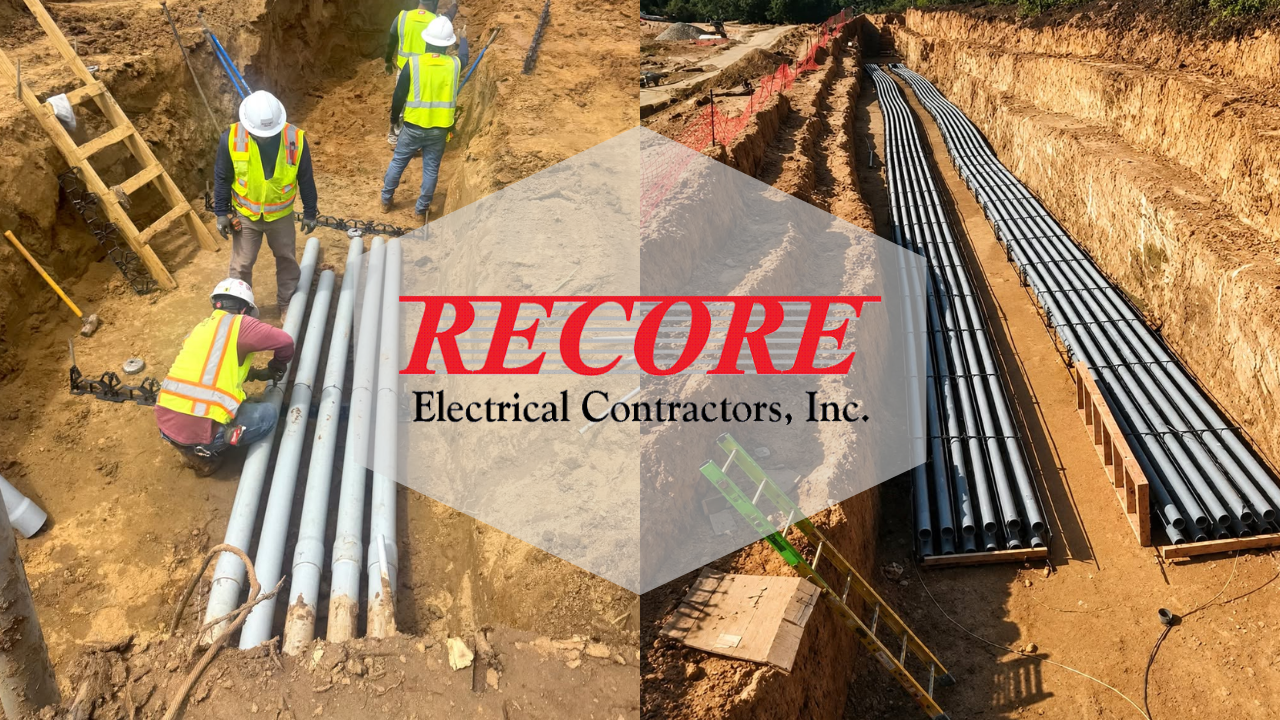
Computer-aided design for industrial electrical work is far more than putting lines on a screen. A complete set of electrical CAD drawings for an industrial facility typically includes single-line diagrams showing the overall power distribution architecture, panel schedules, conduit and raceway routing plans, equipment layouts, grounding and bonding details, lighting plans, and control wiring diagrams.
Each of these documents serves a distinct purpose. Single-line diagrams give engineers and inspectors a bird's-eye view of how power flows through the facility. Panel schedules document circuit assignments, load calculations, and breaker ratings. Conduit routing plans show installers exactly where raceways need to run, what size they need to be, and how they navigate around structural elements and other trades. As-built drawings record the system as it was actually constructed, which becomes the reference point for every future modification, maintenance activity, or inspection.
Recore produces both 2D and 3D models, with 3D work often integrated directly into the BIM coordination process to detect conflicts between trades before construction begins. When a ductwork run and an electrical conduit are scheduled to occupy the same space, catching that conflict in a 3D model costs almost nothing. Discovering it in the field during installation costs significantly more in time, labor, and materials.
The Compliance Dimension: Why Drawings Are Not Optional
Electrical drawings are not just useful project management tools. For industrial facilities, they are tied directly to regulatory compliance and worker safety.
OSHA's 1910 Subpart S Electrical standards govern the design safety requirements for electrical systems in general industry workplaces. These standards require that electrical equipment be installed and used in a manner that is safe for employees, with proper working space, clear marking of disconnecting means, and systems designed to prevent hazardous conditions. During an OSHA inspection, compliance officers expect employers to be able to demonstrate that their electrical systems were properly designed and documented. A facility without current, accurate electrical drawings is in a difficult position to meet that expectation.
The National Electrical Code (NFPA 70), published by the National Fire Protection Association, is the foundational standard for safe electrical installation in the United States. While the NEC is not itself a federal law, it is adopted by most state and local jurisdictions and enforced through the inspection and permitting process. Industrial electrical installations must be designed and documented in a way that demonstrates NEC compliance. Detailed CAD drawings, produced by engineers who understand how the code applies to industrial systems, are how that compliance gets communicated to inspectors, general contractors, and facility owners.
When Recore's engineering staff produces CAD drawings for a project, those drawings are developed with code compliance in mind from the outset, not added as an afterthought. That approach matters enormously during the inspection and commissioning phases of a project.
From Initial Design to As-Builts: The Full Drawing Lifecycle
One of the most common mistakes on industrial electrical projects is treating drawings as a one-time deliverable rather than a living document set. The reality is that drawings need to evolve with the project. Recore's CAD design process follows the work through every phase.
Initial Design Drawings are produced during the planning and engineering phase. These establish the fundamental architecture of the electrical system, including voltage levels, distribution paths, equipment sizing, and load calculations. For new construction projects, these drawings inform the new construction scope and feed directly into permit applications and utility coordination.
Construction Documents are the working drawings that installers use in the field. These include the detailed conduit routing plans, equipment placement drawings, and connection diagrams that tell a crew exactly how to execute the installation. Recore updates these documents in real time as conditions on the jobsite evolve, ensuring that the installation team is always working from current information rather than plans that no longer reflect the project.
As-Built Drawings are produced after construction is complete and document the electrical system as it was actually installed, including any field modifications that occurred during the project. These are among the most valuable documents a facility can possess. When maintenance needs arise, when equipment needs to be replaced, when a power quality issue needs to be diagnosed, or when an arc flash study needs to be performed, accurate as-built drawings are the starting point. Facilities that lack current as-builts often discover that gap at the worst possible moment.
The Software Behind the Drawings
Recore's engineering staff works across multiple platforms to meet the specific demands of each project.
AutoCAD is the industry standard for 2D electrical drafting, used to produce single-line diagrams, panel schedules, site plans, and construction documents. Its widespread adoption means drawings can be shared, reviewed, and modified by project teams, general contractors, and inspectors without compatibility barriers.
Revit is Autodesk's building information modeling platform, used for 3D design and coordination on more complex projects. Revit allows electrical systems to be modeled in the context of the full building, making it possible to visualize how conduit, equipment, and wiring interact with structural systems, mechanical systems, and architectural elements. This is particularly valuable for large industrial builds where multiple trades must be coordinated in a constrained space.
Navisworks is a model review and coordination tool that brings together Revit models, AutoCAD files, and models from other trades into a single environment for clash detection and project review. When Recore is engaged in full BIM coordination, Navisworks is the platform where coordination meetings happen and where conflicts between the electrical model and other building systems are identified and resolved before they become field problems.
The combination of these platforms gives Recore the flexibility to deliver the right drawing solution for projects ranging from straightforward equipment installations to complex new construction for major industrial clients.
Why In-House Engineering Changes Everything
A critical distinction in Recore's approach is that CAD design is handled entirely in-house by our own engineering staff. This matters for several reasons.
First, it eliminates the communication gap that typically exists when design is handled by a separate engineering firm and construction is handled by a separate contractor. When the same organization is responsible for both the drawings and the installation, the design team understands what is feasible in the field, and the installation team understands the intent behind the drawings. Changes and clarifications happen quickly, without the back-and-forth that slows down projects when design and construction are separated.
Second, in-house engineering means the drawings are produced by people who are familiar with the specific industrial environments Recore works in. Textile plants, food and beverage facilities, plastics manufacturers, and other Southeast industrial clients have specific operational demands that influence how electrical systems need to be designed and documented. That contextual knowledge produces better drawings.
Third, because Recore handles service and maintenance for many of the facilities we build, our engineering team has a long-term perspective on documentation. As-built drawings that are accurate and well-organized today make maintenance work, troubleshooting, and future modifications dramatically more efficient for years to come.
Investing in Documentation Pays Off
It can be tempting to treat electrical drawings as a cost center rather than a value driver, something required by the permit process but not worth significant investment. That framing misses the point. In industrial electrical work, drawing quality directly affects construction quality, inspection outcomes, project timelines, and the long-term maintainability of a facility's electrical systems.
A set of accurate, detailed, code-compliant electrical drawings produced by experienced in-house engineers is one of the most cost-effective investments a manufacturing facility can make in a new project or a major renovation. It is also one of the most durable assets the facility will own, continuing to deliver value through every maintenance event, modification project, and compliance review that follows.
If your facility is planning a new construction project, a major equipment installation, or if you simply do not have current as-built drawings on file, contact Recore Electric to talk through what our engineering and CAD design services can do for you.